

阅读本前言以熟悉手册的其余部分。它
提供以下信息:
•谁应该使用本手册
•本手册的目的
•相关文件
•本手册中使用的约定
•罗克韦尔自动化支持
谁应该使用此
手册
如果您负责设计、安装、,
使用SLC 500的控制系统编程或故障排除
4通道模拟输入/输出模块。
你应该对电路和
熟悉继电器逻辑。如果没有,请接受适当的培训
使用本产品前。
本手册的目的本手册描述了安装、接线和
对4通道模拟输入/输出模块进行故障排除。本手册:
•解释如何安装和连接模块
•概述SLC 500可编程控制器
系统
有关更多信息,请参阅编程软件用户文档
有关SLC 500可编程控制器编程的信息。
出版物1746-UM005B-EN-P-2004年6月
2前言
相关文件
以下文件包含有关
罗克韦尔自动化产品。要获取副本,请联系当地
罗克韦尔自动化办公室或经销商。
阅读本文件文件编号
关于SLC指令集的深入信息。SLC 500指令集参考手册1747-RM001
关于如何安装和使用模块化SLC 500的说明
可编程控制器。
SLC 500模块化硬件风格用户
手册
1747-UM011
关于如何安装和使用固定SLC 500的说明
可编程控制器。
SLC 500固定硬件式安装&
操作手册
1747-6.21
关于如何安装4通道模拟输入/输出模块SLC 500 4通道模拟输入/输出模块的说明
安装说明
1746-IN008
有关降低电气噪声的信息。电气控制系统设计
噪音
GMC-RM001
关于接地和接线的深入信息Allen-Bradley®
可编程控制器。
Allen-Bradley可编程控制器
接地和接线指南
1770-4.1
固态和固态之间重要差异的描述
可编程控制器产品和硬接线机电
设备。
固态应用注意事项
控制
SGI-1.1
关于电气接地导线尺寸和类型的文章
设备
国家电气规范-由国家消防局发布
马萨诸塞州波士顿协会。
工业自动化术语和缩写词汇表。Allen Bradley工业自动化
术语汇编
AG-7.1
出版物1746-UM005B-EN-P-2004年6月
前言3
如果您想要手册,您可以:
•从互联网下载电子版本,网址为:
–www.theautomationbookstore。通用域名格式
– http://ab.com/manuals
•订购印刷手册:
–联系当地经销商或罗克韦尔自动化
代表
–访问www.theautomationbookstore。通用域名格式
–拨打1.800.963.9548(美国/加拿大)或001.330.725.1574
(美国/加拿大境外)
常用技术
在本手册中
本手册中使用了以下约定:
•像这样的项目符号列表提供信息,而不是
程序步骤。
•编号列表提供顺序步骤或层次结构
信息
•斜体字用于强调。
您对本手册的问题或意见
如果您发现本手册有问题,或有任何建议
关于如何使本手册对您更有用,请
请按以下地址与我们联系:
罗克韦尔自动化
自动化控制和信息组
技术通信部A602V
P、 邮箱2086
威斯康星州密尔沃基53201-2086
出版物1746-UM005B-EN-P-2004年6月
4前言
1出版物1746-UM005B-EN-P-2004年6月
1章
概述
本章介绍了如何使用模拟,并提供了两个
模拟的应用示例。可用模拟的类型
还描述了模块及其相关规范。
如何使用模拟是指通过
连续物理变量的测量。模拟应用
以多种形式存在。以下应用程序显示了一个典型的
使用模拟。
在此应用程序中,处理器控制放入的流体量
通过调节阀门开度的百分比来设置储罐。这个
阀门初100%打开。当油箱中的液位接近时
在预设点,处理器修改输出以降低闭合
调节阀门以保持设定值。
模拟模块的类型以下各节概述了各种模拟模块
模块。
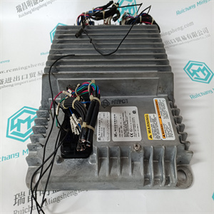
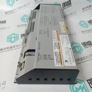
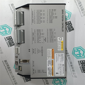
YASKAWA CPS-150F
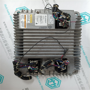
YASKAWA CPS-150F
Read this preface to familiarize yourself with the rest of the manual. It provides information concerning: • who should use this manual • the purpose of this manual • related documentation • conventions used in this manual • Rockwell Automation support Who Should Use this Manual Use this manual if you are responsible for designing, installing, programming, or troubleshooting control systems that use SLC 500 4-Channel Analog I/O Modules. You should have a basic understanding of electrical circuitry and familiarity with relay logic. If you do not, obtain the proper training before using this product. Purpose of this Manual This manual describes the procedures you use to install, wire, and troubleshoot your 4-channel analog I/O module. This manual: • explains how to install and wire your module • gives you an overview of the SLC 500 programmable controller system Refer to your programming software user documentation for more information on programming your SLC 500 programmable controller. Publication 1746-UM005B-EN-P - June 2004 2 Preface Related Documentation The following documents contain additional information concerning Rockwell Automation products. To obtain a copy, contact your local Rockwell Automation office or distributor. For Read this Document Document Number In-depth information on the SLC Instruction Set. SLC 500 Instruction Set Reference Manual 1747-RM001 A description on how to install and use your Modular SLC 500 programmable controller. SLC 500 Modular Hardware Style User Manual 1747-UM011 A description on how to install and use your Fixed SLC 500 programmable controller. SLC 500 Fixed Hardware Style Installation & Operation Manual 1747-6.21 A description on how to install 4-channel analog I/O modules SLC 500 4-Channel Analog I/O Modules Installation Instructions 1746-IN008 Information on reducing electrical noise. System Design for Control of Electrical Noise GMC-RM001 In-depth information on grounding and wiring Allen-Bradley® programmable controllers. Allen-Bradley Programmable Controller Grounding and Wiring Guidelines 1770-4.1 A description of important differences between solid-state programmable controller products and hard-wired electromechanical devices. Application Considerations for Solid-State Controls SGI-1.1 An article on wire sizes and types for grounding electrical equipment. National Electrical Code - Published by the National Fire Protection Association of Boston, MA. A glossary of industrial automation terms and abbreviations. Allen-Bradley Industrial Automation Glossary AG-7.1 Publication 1746-UM005B-EN-P - June 2004 Preface 3 If you would like a manual, you can: • download an electronic version from the internet at: – www.theautomationbookstore.com – http://ab.com/manuals • order a printed manual by: – contacting your local distributor or Rockwell Automation representative – visiting www.theautomationbookstore.com – calling 1.800.963.9548 (USA/Canada) or 001.330.725.1574 (Outside USA/Canada) Common Techniques Used in this Manual The following conventions are used throughout this manual: • Bulleted lists such as this one provide information, not procedural steps. • Numbered lists provide sequential steps or hierarchical information. • Italic type is used for emphasis. Your Questions or Comments on this Manual If you find a problem with this manual, or you have any suggestions for how this manual could be made more useful to you, please contact us at the address below: Rockwell Automation Automation Control and Information Group Technical Communication, Dept. A602V P.O. Box 2086 Milwaukee, WI 53201-2086 Publication 1746-UM005B-EN-P - June 2004 4 Preface 1 Publication 1746-UM005B-EN-P - June 2004 Chapter 1 Overview This chapter describes how analog is used and provides two application examples of analog. The types of available analog modules and their related specifications are also described. How to Use Analog Analog refers to the representation of numerical quantities by the measurement of continuous physical variables. Analog applications are present in many forms. The following application shows a typical use of analog. In this application the processor controls the amount of fluid placed in a holding tank by adjusting the percentage of the valve opening. The valve is initially open 100%. As the fluid level in the tank approaches the preset point, the processor modifies the output to degrade closing the valve 90%, 80%, adjusting the valve to maintain a set point. Types of Analog Modules The following sections provide an overview of the various analog modules.
Copyright ©2019-2022 瑞昌明盛自动化设备有限公司 版权所有 赣ICP备2021006016号